Tuesday, October 6, 2009

Heating and Seating – Interior Part III

Continuing our saga, we’ll focus on removing the heater and the seats and get to the other stuff in subsequent ‘blogs, y’all.

Before I begin, I do have some newses for you. The little news: In real-time, just the exhaust, gas tank, and miscellaneous suspension parts need sandblasting and painting before I can start the ‘Put It Back Together’ phase of my Master Plan. The big news: The body has been painted, ready for delivery. Keeping you in suspense a little bit, here’s a glimpse: The finished hood (can’t see the red pearl coat in the picture, though).

Back to the Past. From previous posts, we’re pretty close to having everything disconnected from the body to, eventually, remove it. Right now, in blog time (sometime around early April ’09), our checklist looks something like this:
- Top: Removed
- Hood: Removed
- Trunk Lid: Removed
- Windshield: Removed
- Interior: About halfway
- Gas Tank: Later
- Engine/Brake/Clutch Controls: Later
- Wiring: Later
- Headlamps/Grill: Later
- Bumpers: Later
- Fenders: Later
- Doors: Later
- Carriage Bolts: Later

This is all just to remove the body (sounds like a lot, but it really isn’t). The engine, transmission, differential, and suspension will be dealt with after the body’s gone.

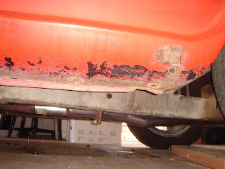
If you’re ready to begin, drain your radiator. If this seems weird to you, then you may need to think about things a little. Remember when you disconnected the heater control valve in ‘Misses Dash - Interior Part II’? Well, that heater valve just controls how much heated coolant is siphoned off the engine to your heater core to provide you with your desired amount of heat. It’s called coolant, but smart folks long ago decided to use it as a heat source too and they’re still doing it. All your heater really is is another, albeit small, radiator that transfers your engine’s heat to warm the air passing through it. So drain your radiator. There will be residual coolant in the hoses and core, but draining your radiator will stop the coolant from coming out of the engine while you’re working on the heater. Got it? Good.

Bonus Material: You might want to flush the system to clean it out beforehand. Depending on how long the car sat, your flushing agent could be just plain tap water or specialty chemicals designed to attack corrosion and gunk in there.

After the coolant is drained and stored in a safe place (pets love to drink antifreeze, but it’ll kill them), start detaching the hoses from the engine. The top hose is attached to the heater control valve, the other hose connects to a pipe that plumbs its way back to the water pump housing. If the clamps are frozen or stripped and the hoses are cracked or damaged, you can cut them - be sure to have something to catch the residual coolant in. When the hoses are disconnected, push them down as far as you can (without crimping them completely closed) to drain what’s in there. After they stop dripping, you can remove the other ends from the coupler that goes through your firewall.

Tech Tip: Get a radiator hose pick tool. It’s just an angled pick with a grip handle on it that you insert between the hose and neck and work it around until the hose is free. This is more for the benefit of the necks than the hoses because most necks that you come across will be copper-based, which is great for heat conduction, but not so great for strength. The pick will save the pliable necks on your radiator, heater core, and pass-through coupler regardless of whether you plan on keeping the hoses or not. A box cutter can be used as a last resort, just watch your fingers, please.

Moving inside the car, go to where the coupler passes through the firewall and disconnect the hoses from it. One thing to remember: The hose from the control valve goes to the top pipe that passes through the firewall, which connects to the hose that goes to the bottom of the heater core on the other side (the hoses cross here). This doesn’t help you at all now, but it will help when you’re putting everything back together. Now, just undo the retaining bolts at the top of the heating unit and set it aside to be dealt with later.

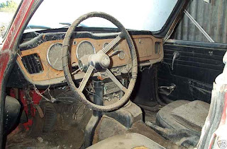
I know you’ve been patient; now, you can remove those pesky seats. There are four bolts holding each in place and you need to tilt both seats forward to find them. See – they’re nestled away in the seat rails. Not much wisdom to offer here, other than making sure that you label/mark the seats for ‘Driver’ and ‘Passenger’ because there are small differences. We’ll tear them down and reupholster them in a later post, but if you want to go with a less-expensive and easier option, junkyards or the Internet may have what you’re looking for: Miata seats. From the research I’ve done, seats from a Miata are the best-fit, modern-day seats for the TR. You can probably find nice, heated, electric, leather Miata seats for what the vinyl seat covers for the original TR4A seats would cost. Since I’m going stock-ish with leather and I like that the original seats don’t come above the door line, I can’t skimp. Your choice, though.

That’s it for now. I think we’ll follow our checklist above and move on to some of those other items next time… Bon Voyage.

Tuesday, September 29, 2009

(Trans)Mission: Possible

In our second installment of automotive tutelage, you’re going to get the shaft. A couple of them, in fact. The drivetrain of a car is full of ‘em: crankshafts, camshafts, input shafts, output shafts, drive shafts, halfshafts, etc. We’re going to focus on the inner workings of a manual transmission (aka: tranny, gearbox, four-on-the-floor): the Input/Output shafts between the crankshaft and the driveshaft.

Before we dive in, let’s discuss purpose. The purpose of any transmission is to use the limited rpm range of your engine and power band to achieve higher speeds and better efficiency. If you’ve ridden a bicycle with gears, you know that lower gears are used for lower speeds, that higher gears are for higher speeds, and that you have to progressively shift through different gears to maximize your own power. You cannot start off in the highest gear and expect to get up to speed quickly nor can you stay in the lowest gear and expect to get anywhere quickly. Gearing makes use of your momentum and allows you to effectively use your power in a comfortable manner. Simplistically speaking, it takes the same power to go 0-5 as it does from 5-10, 10-15, etc. because you just keep adding to your momentum – just like pumping your legs on a swing. OK?

Okay. The difference between your bike gears and a car’s manual transmission is just how they’re laid out – a bike uses a chain and a derailer to go from gear to gear; a car’s gears mesh continuously and are engaged/disengaged to shift. Your front bike gear with the pedals is akin to the tranny’s Input shaft and the rear sprocket on your Schwinn is comparable to the Output shaft. The size in relation to one another is the gear ratio, expressed as output:input. So, if your front sprocket has 17 teeth (or cogs) on it and the rear has 34, the gear ratio is 34:17, or 2:1. (Figuratively equivalent to 1st gear on a mountain bike.) Here’s where it gets a little tricky: you have to interpret the numbers in the ratio as a gear reduction to come up with something meaningful – a 2:1 gear ratio means that every rotation of the output will require two rotations from the input or every rotation of the input results in 1/2 rotation of output. Think about riding your bike in first gear – your legs are rotating much faster than your tires are and, if you actually look at the gears, you’ll be on the smallest sprocket in the front and the largest in the rear – the lowest gear ratio. Progressing through your set of gears, the highest gear you have will relate to the largest front sprocket and the smallest in the rear. This difference in cog counts is exactly what’s going on in your car’s transmission. Replace your legs with an engine and the back tire with a driveshaft and the analogy is complete.

Lab Exercise: In a three gear situation, you have first at 3:1, second at 2:1, and third at 1:1. At 1000 rpm input, these numbers would relate to 333 rpm, 500 rpm, and 1000 rpm respectively. You can see that at the same input, your output is getting faster and faster as the gear ratios are getting larger and larger. Now, if third gear was 0.99:1 (or anything less than 1), your output will be spinning faster than your input and you are now in ‘overdrive’. Overdrive just means that the diveshaft is spinning faster than your engine – a 0.85:1 overdrive would result in 1176 rpm in the example above.

Advanced Lab: Since the differential has an internal gear ratio associated with it, your transmission’s output does not directly relate to your tires' speed. You may have heard of 411 gears, this just means that there’s an additional gear reduction of 4.11:1 in your differential, so at 1:1 in your transmission, it would still require 4.11 rotations of your engine (and transmission) to move your tires one revolution. Since the tires come in many different sizes, another calculation would be required to translate tire rotation to actual MPH (one of which is 2πr, or the circumference of a circle).

Real-World Lab: (The math portion of the lesson is almost over). What would your speed be in 1st, 2nd, 3rd, and 4th at 2500 engine rpm on a stock 1967 TR4A/IRS? Doing some research, you find out that the gear ratios of the TR4’s gearbox are:
First: 3.14:1
Second: 2.01:1
Third: 1.32:1
Fourth: 1.00:1

This would relate to the following output rmps at 2500 engine rpm:
First: 796 rpm
Second: 1244 rpm
Third: 1894 rpm
Fourth: 2500 rpm

Assuming a 3.70:1 rear (differential), the following would be the corresponding tire rpm:
First: 215 rpm
Second: 336 rpm
Third: 512 rpm
Fourth: 676 rpm

Now, given the original tire size of 5.95-15, this relates to an overall radius of approximately 12.75 inches, or a circumference of 80.11 inches. This means that for every rotation of the tires, they will move a distance of 80.11 inches. Since we have the distance per rotation and the rotations per minute, we can come up with total inches per minute and, with some additional math, miles per minute and, finally, miles per hour. As useless as it seems, the answers to the question are:
First: 16.3 MPH
Second: 25.5 MPH
Third: 38.8 MPH
Fourth: 51.3 MPH

What does it all mean? In theory, using the same amount of work from your engine, you can travel over 50 miles in an hour rather than just 16. Correlating this to when you start in the highest gear on a bicycle, the car would have to work very hard to get up to 50 MPH if it only had 4th gear.

I think the horse is dead so I will stop beating it. What you’re really interested in is how that gearbox works. You know that moving the gearshift around changes the gears but the rest is shrouded in mystery. Well, Sir, knowledge is about to be dropped.

Forgetting about Reverse gear for a moment, and remembering that the gears in a manual transmission have a constant mesh, it’s not a tough jump to imagine four sets of gears with varied sizes, approximately being of size that would allow for the ratios described above.

Now, looking at the same gears on their side (so we can arrange them inline), you see that you can have the gears described above rotating in pairs along two common axi (is that even a word?).

Taking it a step further and replacing each axis with a shaft will give you four geared pairs and constant mesh. Keep in mind that the gears are not fixed to the shaft yet so each pair is free to rotate independently.

We now move the pairs close together and assign labels to the shafts – ‘Input’ for the side connected to the motor and ‘Output’ for the side connected to the rest of the drivetrain. The pairs are still free to rotate on the shafts.

Making it a little more useful, we now affix the upper gears to the Input shaft. This is typically accomplished by having a splined shaft. We haven’t done anything to the Output shaft yet, so if, let’s say, the engine is running at 2500 rpm, the Input shaft will be rotating at the same speed, the Output gears will be rotating at various speeds (see below), but the Output shaft will stay dead.

Adding something to the Ouput shaft, specifically synchros, will give us a way to ‘engage’ the gears one at a time. Shown here, the transmission is figuratively in Neutral. The synchros can slide back and forth and there is a mechanism there on each surface to engage a gear when they meet. So, with no gears engaged, everything is still spinning with the exception of the Output shaft, as shown.

Finally, we shift into first. Neglecting clutching for our example, only the first gear is coupled to the Output shaft through the synchro and it’s spinning at almost 800 rpm.

So, we have the engine at 2500 rpm, the power is going through the Input shaft, meshing with the Output gears, first gear is engaged, thereby powering the Output shaft at 796 rpm, going through the differential to do more math and the car is cruising at 16 or so miles per hour. Let’s switch to second.

Now we’re at 25+ MPH. Third.

Approaching 40 MPH, the tranny’s output shaft is humming at almost 2000 rpm and we switch to fourth.

I think you get it. Wrapping up the lesson, the clutch is a mechanical link between the engine’s crankshaft and the transmission’s Input shaft. Along with mechanisms in the synchros and the gears themselves, the clutch’s job is to disengage power to the Input shaft so that switching from gear to gear doesn’t result in grinding. (By the way, since the gears are in constant mesh, grinding is not actually your gears but is rather from synchro to gear malignment.)

Oh, and as for Reverse, there’s an additional ‘idler’ gear that slides into place, reversing the direction of the Output shaft, seen here:

One last diagram of the actual TR4's gearbox. Looking from the top, the Output shaft is above the Input shaft (so the Input shaft is hidden), the clutch/engine would be to the right and the driveshaft/rear would be to the left. The 'mechanisms' that interact between synchros and gears are also seen here - they're called 'Dog Teeth' of all things.

May I squeeze in a final tidbit of information? If you notice, the Reverse Gear and Idler are straight-geared and the rest are angled. The angled gears reduce noise and mesh better than the straight ones. You've all heard the whine when you go in reverse - that's from the straight gears! Why not use angled for Reverse? That Idler would have a hell of a time sliding in and out if it were angled.

Friday, September 25, 2009

Misses Dash - Interior Part II

By now you have a project on your hands. I’m not sure, in the grand scheme, when, exactly, something becomes a project, but I’m willing to bet that a ’67 sports car that’s missing most of its top side and half its interior qualifies. So now what? To save your project from becoming just another boxed-up bargain listing on eBay, you gotta maintain expectations and be adaptable. Knowing that everything is not going to turn out as planned will keep your sanity in-check and your interests high. So…you find a crack in your differential mount. Big deal. Get a welder, learn to weld, and fix the darn thing. And have fun doing so.

Inspirational words and uplifting sentiment aside, dashboard removal can be quite a task with lots of wires, controls, gauges, and steering columns (er...column) in the way, coupled with intriguing design details that toy with your problem solving skills. Choice time: Do you trust your skills enough to put back together whatever it is that you take apart? If so, read on, Jack.

First things first: Unhook the battery. It’s only 12 volts so you’re not going to get shocked while you’re fiddling around behind the dash, but you could have some nice sparks and arcs if there's power back there. The lead going to the ammeter is live even with the ignition turned off (most of your car’s power goes through here and, consequently, you will not have any power to the rest of the car while the ammeter is disconnected). If you choose to remove the battery entirely, don’t leave it on the floor of the garage or anywhere else near the ground. Mystical forces are at work here and they will drain your battery dead if you let them – a couple of 2x4’s or a shelf will provide adequate insulation.

Before getting down and dirty, there are some prerequisites for dash removal:
- From the engine compartment, free your choke, hood release, and heater control valve cables from their respective mechanisms and feed the cables through the firewall into the car’s interior. You can use a Sharpie to mark the cables as a reminder of position when you reinstall them. Or not.
- Unhook the cable that goes to the heater unit under the dash – the one that controls air flow direction, not that there’s much of a choice there.
- Disconnect the control rod for the vent cowl (one of my favorite features of the TRs is that popup cowl) from the armature under the dash.
- Remove washer fluid lines from under the dash.
- If your vehicle is outfitted with a radio, please unhook it and/or get rid of it now (we’ll be discussing the sound system in a later post).

Now start disconnecting the electrical leads to the steering column under the dash, which consist of wires for the horn, directional switch, light switch, and, in some cases, the overdrive switch. Unless there’s an abnormal amount of deterioration under there, the connectors should separate cleanly with moderate force. Once you think you got all the wires, double check and move back into the engine bay.

Follow the steering column from the firewall toward the rack/pinion and stop at the first joint you come across. Douse it with CRC and loosen the retaining bolt until you have a decent amount of play there. Go back under the dash and unbolt the bolts along the column. Once unshackled, the whole assembly, steering wheel and all, should slide through the firewall and into your pants, setting up a ridiculous scenario in which you squint an eye and say to your buddy, “Arrrg, it’s drivin’ me nuts!”

When playtime is over, you should have a nice amount of room in front of and behind the dash to start removing the gauges, speedometer, and tachometer. Some masking tape and a marker will help since you really should label all the electrical connections before unplugging them.

Although the ammeter, fuel, and temperature gauges are the only ones that work on electricity, all of them have lighting in the form of a pressure-fit bulb. Pop those out, disconnect connections and unhook cables behind the dash, saving the oil pressure for last. Since this gauge is fed directly by the engine’s oiling system, there is a chance residual oil is in either the gauge or the tube or both. Just have a rag handy when you disconnect the oil line. Also inspect the connection for seepage, which could indicate cross-threading or other issues preventing proper sealing. Once the stuff is disconnected, it’s a matter of undoing a couple hand-tightened nuts that secure a U-bracket holding each assembly in place (the ashtray is mounted the same way). The gauge faces are glass, so keep them safe from harm. Don’t worry about whether the gauges are in good working order because we’ll cover how to test all of them in a later post.

So, now you should have an empty dash with wires/cables dangling beneath it. Good progress. When you’re ready, open the glovebox door and remove the glovebox liner – it’s cardboard-ish and should be held in by 6 screws. If you can’t work it completely free, don’t worry; just let it sit in the recess until the dashboard’s been removed. There should be five screws about the dash surface – you remove these and your wooden dashboard will follow.

The dashpad top is next, held in place with glue and a few screws, which are revealed when the wood dash is removed. You also need to unbolt the defrost vents from the underside. What you’ll be left with is the backing plate and the rest of the support structure – don’t be concerned with the surrounding dashpads or the vent ducts – they’ll all come off with the backing plate.

Now you can start tackling the rest of it - move on to the dash support, which is the console-like appendage that holds your radio, envelops the gearshift, and doesn’t really support the dash a whole lot. Undo the four bolts securing it to the floor and then move on up to the plinth. The plinth is the thing directly above the support that holds your controls. Why ‘plinth’? Because Triumph said so. There’s a fastener behind the plinth on the left side – unscrew it and remove the plinth, controls and all, revealing two more bolts on the dash support. Unbolt those and remove the support. Work the fasteners on the backing plate until it can be removed and, Viola! If it wasn’t a project before, it sure is now.
Here's what everything should look like now.

Thursday, July 2, 2009

Panelectomy - Interior Part I

Taking stock of where we are: Hood, windshield frame, top, and trunk lid removed. Taking stock of when we are: About 14-15 March 2009. Since I decided to start The Blog after most of the demolition work was complete, the beginning posts (this one included) will be a couple of months off. (Psst: In real-time, the bodywork is done and it’s in final primer - paint should be applied soon, the engine is almost put back together, I have a bunch of brand-new parts in boxes, and my walk-in sandblasting/painting enclosure is complete.)
So there I was, looking at an orange-ish, faded red, semi-stripped down ’67 TR4A knowing that everything was going to be dismantled eventually, but wondering how to put the work into some level of orderly chaos. I had been working from a top-down approach and I was noting what needed to be done to separate body from frame.
- Hood? Check
- Windshield Frame? Check
- Top? Check
- Trunk Lid? Check
- Dash, Wiring, Seats, Steering Column, Doors, Fenders, Body Chrome, Gas Tank, Seatbelts, Bumpers, Grille, Heater, Interior Panels (what was left of them), Kick Panels, Linkage, etc.? Nope

Today, we will focus on the interior and door panels - after a short introductory tangent…

Even though the seats are some of the easiest things to remove on the car as a whole, you may want to leave them in for a while so you have a place to sit while taking stuff apart in the surrounding area. Also worth mentioning now, during preamble, is the door jamb seal. In the previous post, ‘The Bonnet, to Boot’, I neglected to point out that this seal goes all the way up the windshield frame so some of it will need to be removed before getting here. As with much of the pieces/parts removal, please inspect the seal prior to pulling the ripcord – replacement costs are typically directly proportional to the amount fun had taking something apart. The seal consists of an outer ‘furflex’ material (it’s just furry/fuzzy rubber stripping that keeps noise, wind, and water ingress to a minimum and, to an extent, keeps your doors from rattling) and an inner steel-reinforced strip that secures into the seal channel along the door recesses. Removal is just a matter of working one area loose and pulling until you get it all off. Fortunately, my ramblings have not strayed too far from the topic. Getting back to the panels…

By now you should have a nicely-accessible cab to work in without the hindrances of the windshield or convertible top (or surrey top if that’s what you’re into). The interior panels on the ’67 TR4A are not very sophisticated in the fastening department. Aside from screws and glue here and there, the only unobvious fasteners are those that hold the door panels on. So, after you’ve unscrewed the kick panels (the panels under the dash directly forward of the doors), quarter trim panels (those right above the wheel wells), and rear bulkhead board (I think you can figure that one out) you should be left with glued-on vinyl trim stuck to both wheel wells and ‘B’ posts (we’ll get to the door panels in a minute). There is a nice, big, shiny bolt that holds your seatbelt in the middle of each wheel well in addition to two eye hook bolts on either side of each seat. For now, just remove the chromed bolts on the wells and leave the eye hooks on the floor pan and ‘B’ posts.

Intermission Time: The car’s posts are the vertical support structures found forward of and behind each door. On the TRs, the front posts, holding the door hinges, are ‘A’ posts and the back ones, holding the door strikers, are the ‘B’ posts. Unimaginative as it may be, a four-door car would have a set of ‘C’ posts, normally housing the striker assemblies for the rear doors (the ‘B’ posts would share front and rear door duties). Limousines could have more exotic letters in their posts’ names, but we don’t have all day here.

Regardless of your post situation, we’re left with removing vinyl from them and your wheel wells. They’re just glued on, but the wheel well coverings have some troubling material behind to add padding and plush to the décor. There’s really no secret here, just scrape, pull, swear, and sweat. You could leave remnants, just enough to provide a good base to hold new glue – a wire brush would be good here.

The door panels! Each door panel will have some obvious screws (that may or may not have plastic caps on them) and some hidden tricks that will surely frustrate you to no avail. Before going further, please get/borrow a 90° pick and a door upholstery remover tool (both pictured below).

After removing the screws (including the swinging door-shut knocker), make sure the window is rolled down because we’ll be removing the window crank and door handles. They’re spring-loaded and are held in place using a pin/collar arrangement (see photos below). With your door secured (either fully shut or fully opened), press the black plastic collar surrounding each base on the crank/handle far enough to see their ends. Now, there will be a pin going through one side of the base straight through to the other side – it’s tapered so you’ll need to feel around with that 90° pick until you find the correct side and work it out. Repeat until all handles are off their respective nubs. The second, appropriately named, tool should then be used to pry the hidden clips underneath the perimeter of the door panel. Work it like you’re trying to open a pan of caint. Or, a can of paint. Again, taking care to find the clips before prying if you plan on keeping your door panels intact – otherwise, I suppose a screwdriver and brute force will work just fine. The last part is getting rid of the arm pads along the top of the door frame. They’re just glued on so if you remove them, plan on getting new ones because they’ll get a bit chewed up while removing them. When the doors are free of their dressings, you can sit back and survey your accomplishments, recall feelings of uncertainty, and pay homage to the determination that got you here.

The Aforementioned Tools

Spring-Loaded Cranky Handle

Beat-up Door Panel and Clips

Tuesday, May 26, 2009

The Bonnet, to Boot

Continuing from the ‘Body of Evidence’ post, we had a level of indication that the body is in decent shape, let’s move on…

…The hood (bonnet, if you’re British) was out of alignment and showed signs of damage from a stuck hinge. To reduce further damage, it was just about the first thing that was removed from the car. Not having the luxury of friends around to help, I made my own. I looped a rope over a rafter in the garage above one side of the hood, making a big circuit from rafter around the hood and back - the headlamp arch in the hood itself acted as a nice catch for the rope and prevented it from moving too much. Removing the prop rod assured me that the rope would hold and I proceeded to unbolt the hinge on the roped side first. (Be sure to unbolt them from the hood-side connection rather than the inner-fender-wall side, it may be a little more difficult to loosen the bolts this way, but the hood will be far easier to remove without the hinges dangling about.) After removing the bolts on the other side while supporting the hood with my free hand, it was just a matter of repositioning to get a hold of the entire thing and then sliding it out of its crude cradle. Have an idea of where you are going to put the hood beforehand – it’s more awkward than it is heavy, but preplanning here could save some amount of improvisation and indecision later. Getting the hood out of the way early will really open the engine compartment, allowing unfettered access to inspect and/or repair a lot of them car parts.

And for those of you wondering about that stuck hinge – I soaked it in CRC (similar to WD-40, but way better) overnight and pounded the spit out it with a convincing hammer, only to wind up with an oily, bent, stuck hinge. I was able to find a used one on eBay that worked.

Waaaait a minute: That hinge’s resilience to budge could have easily been blamed on corrosion – and it was, until just now. Writing about it made me think more about it and question, on a virtually rust-free car, how it could have gotten to the point of seizure through oxidation? Moreover, I remembered that some of bolts on the left hinge (driver's side) were loosened to act as a pivot point so the hood could still open and close, but - the hinge was stuck in the OPEN position, cocking the hood upward on the driver's side when closed.  See...


There wasn’t rust in the surrounding area, the hinge was stuck open, there was visible evidence of a half-assed repair; the synapses started firing. Those of you who know how arc welders work (the actual equipment, not the people), know that the business end is just a node that completes an electrical circuit and that the welding machine works by delivering a large amount of current through a spark (or arc), which heats up the metal and the welding material into a molten stew that, when cool, binds everything together in what’s called a weld. The welder is also supplied with a clamp that must be electrically connected to the metal you are welding, acting as a ground in the circuit. Now, here’s my theory: Someone unwittingly welded that hood hinge in the open position. Since the hood doesn’t really have much exposed metal to provide a good electrical path for the clamp, it was probably secured to the frame or other part of the body while doing the repair work (with the hood up). Since the current had to travel through the hinge, which has gaps between moving parts, these gaps caused their own weld sites and, Viola! mystery solved. I’ve heard of this happening with car door hinges, so it’s really less mysterious that you may think.

Back to it: After the hood was off, I looked at the hood. Rather, after the bonnet was off, I looked at the hood. In Britain, the car’s top is referred to as the ‘hood’, the windshield ‘windscreen’, and trunk equals ‘boot’. So, from front to rear, you have the bonnet, windscreen, hood, boot. To avoid confusion and to minimize pompousness, the good ol’ American terms will be used from now on: ‘hood’ shall be forever read to mean ‘engine cover’, the rest I leave up to your interpretation.

Back to it, again: Looking at this raggedy mess that was once a convertible top, I decided that it was next to go. Before getting rid of the top material, I did a survey of the bows: this is the assembly that supports the rag top and does the moving from up to down, down to up. Sitting for such a long time, the joints were a bit arthritic and resisted my attempts to unsettle them. My old friend, CRC, worked in this case because it was just some rusty/dry hinges and connections that needed oiling. And, just like the Wizard of Oz’s Tin Man, I had them joints back to what they once were in no time. Once ‘up’, removing the worn-out vinyl top was pretty straightforward because I knew none of the material was salvageable: rip, cut, pull, tear. There are two strips of material, known as ‘webbing’, that are connected to the top assembly (bows) from front to back. If yours are not in bad shape, try to keep them because they are typically not included when you order a new top (they’re also available new for less than $10 each, so - your choice). Once the bulk of the material was gone, I moved on to the more-delicate task of removing the bow assemblage. First, there was a retainer bar that holds the back of the top material to the car itself – just a matter of peeling back the remnants of the top and unbolting some, well…bolts. The next part of the operation was to unscrew some, well…screws (yes, screws) that hold the bow assembly to the chassis. 42-year-old screws are not a welcomed site. 42-year-old screws tend to strip easily. 42-year-old screws are a pain the ass. Pushing negativity aside, I dove right in with an impact driver and, to my surprise and delight, all six of those retaining screws came right off with little to no coercing. The bane of the 42-year-old screws would really only present itself once, later. Finding a nice, quiet corner of the garage, I set the bows and associated hardware down to be forgotten until this Phoenix of a car rises from the ashes in a Triumph-ant display of fortitude, beauty, and dollar signs.

A word to the wise, or at least to those listening, they say that experience is what you get by not having it when you needed it. With this in mind, rather than tearing into the car like so many flying monkeys on a scarecrow (I hope this is the last Oz reference), take your time to look at parts that can be repaired/restored. Although many new parts are available for these old cars, some are relatively expensive ($1100 for a quarter panel??) and some are just plain unavailable, as described below.

Next up: the windshield and frame. The windshield glass on my particular ’67 TR4A was in very nice shape - the glazing (the black gasket that holds the glass in place) wasn’t. The once-pliable glazing gasket had better days, I imagine. It was dry and cracked with remnants of yellowed glue here and there and some sort of sealer (caulk) smeared in where chunks had gone missing. What appeared to be a valiant effort by a previous owner decades ago was now a disheveled mess, undermined by California sunlight, dry weather conditions, and ultimately, time. Lucky for us, new retaining gaskets are available and are less expensive and easier to replace than most people think. Removing the glass is a matter of running a utility knife around the perimeter of the glass, about midway on the gasket (ideally, right at the edge of the glass), cutting into the glazing as you go (#2 in the diagram below). It will take a little bit of work, but once the glass is free, the gasket should separate from the frame with ease. Putting it all back together will be another topic at another time. We’re getting to the ‘unavailable parts’ mentioned earlier so hold on. Now that the frame is free of the glass, we can start removing it. Triumph's original idea was to make the windshield frame a removable piece so that you could legally drive your TR4 to the race track, take off your windshield to get some laps in, and drive back home with your windshield re-attached. Oh, the ‘60s. I cannot claim to remember them on account I wasn’t born yet, but from what I’ve heard, this windshield scenario fits right in. Adding on to its design, removal of the windshield frame is necessary if you’re planning on replacing your dash pad and is a good way to make some room for doing just about any type of work in that general area. Aside from the three chromed bolts visible on the inside lower edge (#7 in the diagram below), there are brackets just under the dash on each side above the kick panels in line with the angle of the windshield (unnumbered). The windshield post is threaded and is secured to these brackets two ways: a nut on the end of the post (#21) and a retaining bolt that clamps down on the post (#17). Once all the nuts and bolts have been removed, a swift rap on the end of each post along with working the frame back and forth will dislodge it from the bracket and break any hold the #5 gasket has left in it. The brackets are bolted to the body and can remain there if the remaining bolts are left unmolested.

Now. The windshield frame has a thin plastic trim around it on the interior side that almost looks like a thick paint, but it's plastic (not pictured). I assumed that this finishing trim would be something relatively simple to find and would have probably just been included with an interior kit. Nope. Can't find it. This may come as a disappointment after the literal build up on parts availability, but it serves as reminder every time I think of it to take my own advice and look before you leap, know what parts you can scrap and which ones to be careful with. I have no doubt there will be more stories, but let's get back to business.

The trunk lid removal was uneventful and, aside from closing out this post, there’s not too much to talk about. The design is a little curious, in that there’s a tubular support thingy in there making you wonder about the original blueprints and what must have transpired to endorse this afterthought. Oh, and I like the ratcheting stay rod, which should be disconnected prior to undoing the nuts on the backside of the trunk hinges, thereby detaching your trunk lid completely.

Here are some pictures for your viewing pleasure while I come up with my next topic (taken on 3/17/09):


Tuesday, May 12, 2009

A Diversion

In an effort to keep these postings interesting, some blogs will stray from the task at hand and offer some level of general insight into the automotive field. Refraining from ‘Science Content’ warnings or Nerd Alerts, I will try to present technically-riddled subjects in contextual format with my own brand of whimsical nonsense. I don’t think the physics behind air/fuel mixture vortices would provide much value unless reflecting upon a certain Honda’s ancestral roots and the Compound Vortex Controlled Combustion (CVCC) engine that it sported. But, I digress with purpose.

You’ve heard of the Honda Civic and you’ve also heard terms like V8, Straight Six, Cubic Inches, Liters, 4-Stroke/2-Stroke, etc. when referring to automotive engines. Aside from sounding neato, these are all useful in determining what you’ve got under the hood (bonnet, if you’re British).

V8 refers to two things: 8 cylinders in a V formation – that is 2 rows of 4 cylinders set at an angle to each other (a V6 has two rows of 3 cylinders and so forth). Straight/Inline is an arrangement of 1 row with all cylinders lined up: I8, I6, I5, I4. Since the ‘70s, American manufacturers wandered from the standard straight six to pursue V6s and never looked back. The choice was made for economical reasons, rather than performance reasons and many auto makers have followed. I6s are still out there, though - BMW has built quite a reputation on theirs (the “i” following most of their model numbers means inline). Engine configurations are not limited to Vs and Is - there are many more including (but no limited to) Slant, Flat, Opposed, W, and H, but I’ll let The Internet answer your questions on those. All of these types of engines have their benefits and drawbacks and are very useful in certain applications.

Intermission: The Parts of an Engine
Depicted below is an exploded view of an Inline 4, similar to the TR4A’s engine. The cylinders are merely guides for the pistons to move up and down in. The pistons go through strokes to achieve power:
1. Intake Stroke: Down, sucking air/fuel mixture in.
2. Compression Stroke: Up, creating compression – the spark plug causes detonation at the top.
3. Combustion/Power Stroke: Down, pushed from the ignition/explosion.
4. Exhaust Stroke: Up, pushing out spent gasses; and back to 1.
Each piston is connected to the crankshaft, which translates the up-and-down to rotation. The crankshaft is also connected to the camshaft, which controls the timing of intake and exhaust valves. This is all shown in the second graphic, which I obtained from howstuffworks.com.


Engine displacement is measured in cubic inches (CI) or liters (L) and represents the volume of all cylinders added up - it’s a measure of the amount of total space available for internal combustions or, simply, how much explosive force can be transformed into motion. Forgetting about many other aspects that factor into torque and horsepower, the size of an engine is the most basic gauge to how ballsy it is. By numbers alone, it seems logical that a Chevy 350 (that’s 350 CI) would be more powerful than Toyota 2.0L, but what about a Buick 215 versus a Ford 5.0L? A 1-liter engine would equate to about 61 cubic inches and each 100 CI equals roughly 1.639L, so you’d need to level the playing field for comparisons. Also, ad men get into the mix sometimes and screw up the math: the Ford 5.0L is closer to a 4.9L since it’s just a re-badged 302, but 5.0 sounds so much better than 4.9. A more-precise habit of manufacturers and automotive enthusiasts is to use the cubic centimeter (cc) to refer to an engine’s volume: 1L = 1000cc’s. This curious method is what Triumph used, so I will talk about the TR4A’s engine as a 2138 cc instead of a 2.1L or a 130 CI.

Strokes were brought up earlier and they will be the last item of discussion for this journal entry. If you notice, the verbiage describes four diff’rent strokes. What I’m talking about, Willis, is a 4-stroke engine. The neat and orderly separation between these strokes is good for emissions, but not so good for power. Thinking more about this, a complete cycle requires the crankshaft to rotate two times - during which, there is only one power stroke per cylinder. The four-cylinder engine pictured above would have four explosions for every two revolutions of the crankshaft so you’re getting two explosions per revolution. Now, here’s the interesting part: a 2.5L Inline 4 produces as much power, per cylinder as a 5.0L V8. Since only one cylinder fires at a time and individual cylinders are the same size for both engines – the V8 just has more cylinders, which means more explosions per revolution and, therefore, more total power. The 2-stroke engine is similar to this comparison because there are only two strokes per cycle rather than four - so, you’re getting more explosions per cylinder per revolution - all cylinders have their power stroke every revolution of the crankshaft. Taking it all in, a 2-stroke, 4-cylinder would potentially match the total power of a 4-stroke V8 twice its size. But, because of the nature of mixing exhaust with fresh air/fuel and the need for oil to be mixed in with the fuel, 2-stroke engines are dirtier and produce more harmful emissions than comparable 4-strokes. A visual aid for this comparison:

Wednesday, May 6, 2009

Body of Evidence

After the initial test drive and photo shoot circa March 8th, 2009, the car was quarantined to the garage to begin the restoration process: Take it apart, Fix it, Put it back together – simple enough, right? (Insert your own foreshadowing now.) Where to begin?

Before taking the car apart, you need to decide what kind of car you want: Show Car? Everyday Driver? V8 Conversion? I wanted something that would look nice with some modern convenience; I wanted to be able to drive the car AND be able to make some money if I decided to sell it. So (drum roll, please)…this will be a mostly stock, original-ish frame-off restoration. So let’s get started.

Assessing the condition of my new toy car:

This particular 1967 TR4A IRS spent most (if not all) of its life in the high desert of Southern California. It was, therefore, in pretty good condition rust-wise – it was not, however, in as great condition when it came to the interior, paint, seals, gaskets, top, seats, dashboard, etc. since it basically sat in a shed for 14 years. The engine had some new parts and came with the possibly spurious promise that ‘the previous owner rebuilt it’. It didn’t smoke, knock, ping, or otherwise sound bad so I took it at face value, knowing most of the motor needed to be taken apart anyway to replace leaky seals/gaskets – but we’ll get more into that later. It had 71,577 original miles and, based on the condition, I didn’t (and still don’t) doubt it. Right now, I’ll focus on the body and get to other parts in subsequent posts.

A visual inspection only revealed one small rust hole in the bottom of the right front fender that carried through to the rocker panel. Seriously? Just one, small bit of rust? Tapping around and feeling behind panels was just as promising. How much rust and filler was hiding under paint or otherwise not seen?

Tip #1: A little magnet will uncover more about a car’s history than anything else. Since a magnet will not stick (or at least not stick as well) to filler/Bondo, it’s a great tool to check the condition of your body panels. You can easily roll one of those little, round magnets around wheel wells, across rocker panels, or in any other suspicious-looking areas on the vehicle. And, since it rolls, you won’t leave scratches on the paint (good for not angering owners when you’re checking out a car for purchase).

The magnet revealed some filler in the hood (bonnet, if you’re British) and around the right front wheel well, both of which were attributable to dent/ding/repairs rather than rust.

All in all, the total body damage assessed was:
- Right Front Fender/Rocker Rust
- Right Front Fender Body Filler (assumably from a dent)
- Hood Damage/Repair/Filler from Weld Fracture (due to frozen hood hinge)
- Surface Rust and Filler on Hood around Headlamp Arches
- Floor Dents from Misplacement of Jack
- Slight Trunk (Boot, if you’re British) and Rear Valance Damage (presumably from a minor rear end collision)
- Surface Rust in Trunk
- Various Dents and Dings

The consensus for the body: I couldn’t believe it was a ‘67. 42 years old with only about 4 square inches of rust? I hated to admit it, but this car’s body was in better shape than mine. This theme continued as I disassembled the car.

These pictures, taken on March 31st, show the condition of the body. It had been repainted a few times and much of the poor-quality black paint was peeling away under the hood and in the trunk.

Lonely Rust on F/R Fender
(Black is Primer)

Solid L/F Fender

Filler on R/F Wheel Arch

Damage & Shoddy Repair on Hood

Solid, Denty Floorboard

Rear Trunk/Valence Damage

Slight Surface Rust in Trunk Floor (and bad paint job)

Just a Shot Showing Alignment of Left Door/Fender

Friday, May 1, 2009

That Ain't No Bronco

Those who know me, know that I've been in the market for an Early Bronco (1966 - 1977) to restore and have fun with for a while now.  I almost had my mind made up when a question of logistics was curiously raised while looking at my garage space.  My 1940's-era 1 1/2 car garage was not going to accommodate 36-inch tires and a 5-inch body lift on an already-rather-tall truck.  Oh crap.

With the desire to get my hands dirty, I started looking at Camaros, GTOs, Chevy IIs, and other muscle cars.  Knowing full well that my budget would not go very far, the results were ominous.  With prices for a rusted-out heap sans drivetrain averaging $10k, I was going to need another plan: foreigns.  

Porsche?  Yeah, right.  
Datsun?  Not cool.  
VW?  Not interested.  
Sunbeam?  More expensive than I thought.  
MG?  Perhaps.  
Triumph?  Possibly.

Looking on eBay, my mind was made up.  The old Triumph TRs were still relatively inexpensive and, doing more research, replacement parts were available and reasonable.  I looked at a few TR6s, but the TR4s really caught my eye.  What's more, there was one for sale about an hour away that claimed to be rust-free.  All signs were good.

Since I purchased my 1967 TR4A IRS, I have a new-found respect for these old British cars.  Being borne from wartime surplus parts and, eventually, finding a niche in sportscar racing, the TR's evolution is an interesting course.  But more on that in a later post.

Courtesy of http://www.vtr.org/models.shtml, the TR Line: 

TR2 (1952-55)

TR3/3A/3B (1955-62)

TR4 (1961-65)

TR4A (1965-67)

TR5/250 (1967-68)

TR6 (1969-76)

TR7 (1975-81)

TR8 (1978-81)

Wednesday, April 29, 2009

First Post

This blog is set up to provide tips and experience during a frame-off restoration of a 1967 Triumph TR4A Independent Rear Suspension (IRS).

The car, which I found in the high desert of Southern California, was a barn find that the previous owner had his eye on since 1996. I was told that the engine was rebuilt prior to being put in storage...we'll see about that.

After he bought the car in 2006, he did some work to it:
- Thorough cleaning
- Re-powder coated the rims
- New tires
- New Weber DCOE-9 carbs
- New TWN intake manifold
- New Kirk racing exhaust header
- Rebuilt master cylinder
- Changed fluids
- New belt/hoses
- New fuel pump
- New points

I found the car on eBay, it was listed because the current owner had purchased a more complete '67 that had overdrive. After a short trip out to the desert, I verified that it was, truly a rust-free survivor and the story begins.

The pictures below chronicle the condition the car was in when I received the title (with 71,577 original miles) and trailored it home on 3/8/09. It started, drove, and stopped OK, albeit not in trustworthy condition for highway driving.